The dome electronics on the front consist of two blue/white panels, called front logic displays (FLDs), the holo projector, and the red/blue process state indicator light (PSI). On the back there is a rectangular green and red led panel, called the rear logic display (RLD) and a green/yellow PSI.
The lights are controlled via an arduino micro. The micro is connected directly to the RLD. The PSIs and FLDs are daisy chained to all run off of the single arduino.
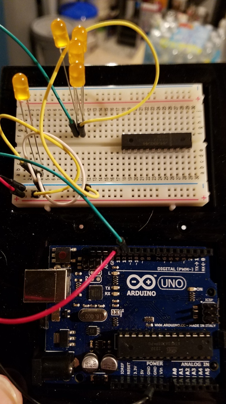
First step is to ensure the LEDs function. I put together a simple test using an arduino UNO to test the LEDs.
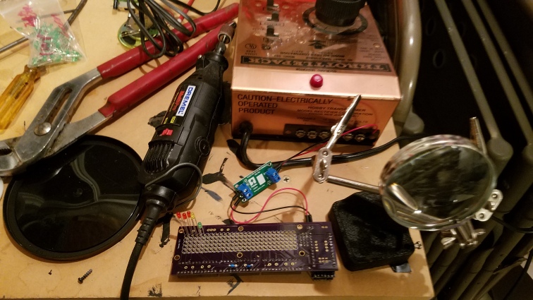
Then was on to assembly of the RLD:
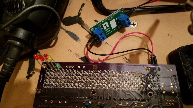
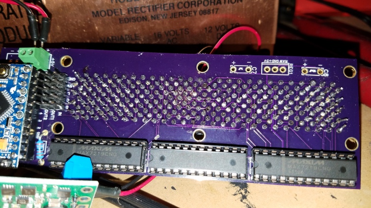
Note in this picture you can see the Polulu power regulator that I use. Instead of building in a power regulator I went with this stand alone model. I chose this because I’ve heard of some negative reviews on the on board regulators failing. The Arduino is located on the opposite site of this board.
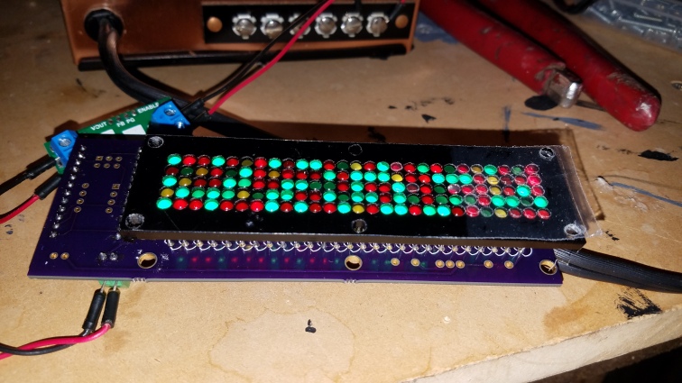
Assembling the LEDs in place.


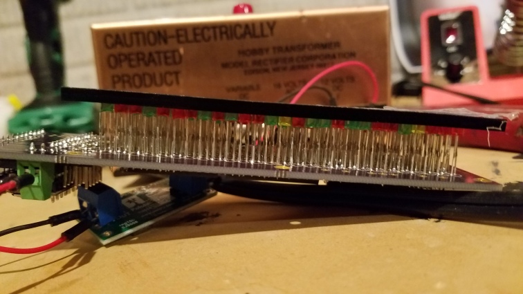
Note the power supply in the background. That is an old HO model train transformer I’m using to power the RLD. Also making sure the LEDs are the right length to fit in the bezel BEFORE soldering.
It was a good idea to not solder the LED controller chips directly to the board. These chips had a bad failure rate. I replaced 5 or 6 of them due to failure. Here is the picture with the three MAX chips with the Arduino when soldering was complete.
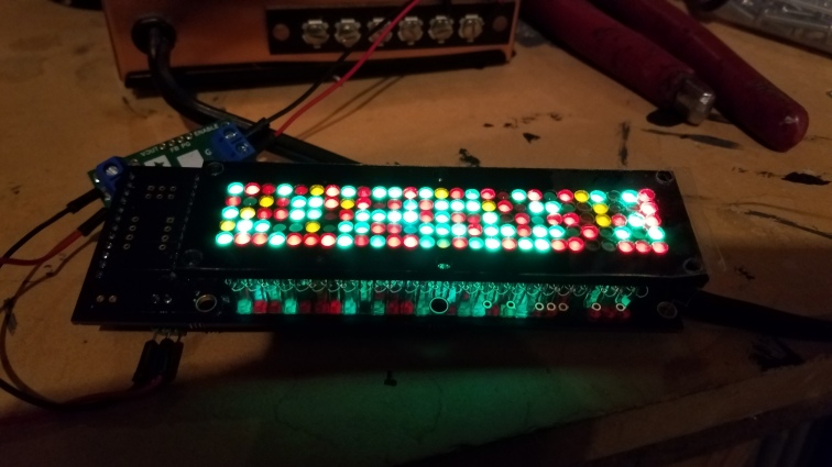
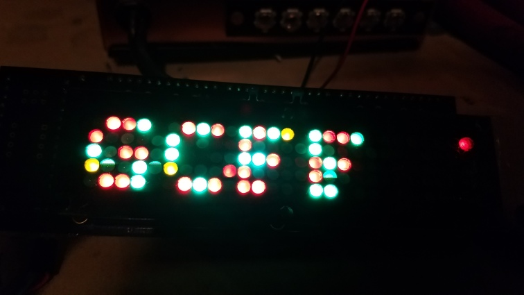
Successful test run!
At this time I have not done any work on the holo projectors. The FLDs and PSIs are now complete as well. Attaching a couple pictures of those. I didnt snap enough throughout the build of each of these. Again massive failure on the MAX chips. Glad to have the sockets to plug them in and that they were not soldered directly to the board.


